User:Hcao: Difference between revisions
| (23 intermediate revisions by the same user not shown) | |||
| Line 22: | Line 22: | ||
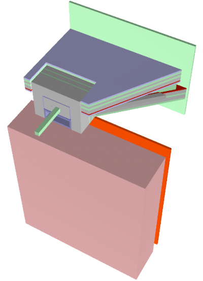
[[File:ShieldingHouse.png| | [[File:ShieldingHouse.png|400px|left|thumb|STM Shielding House.]] | ||
Because the strong radiation flash (consisting of muons, electrons, neutrons, X-rays and gamma-rays) overwhelms the electronic rate capability and causes radiation damages to detectors, the STM detectors need to be protected in several ways. | Because the strong radiation flash (consisting of muons, electrons, neutrons, X-rays and gamma-rays) overwhelms the electronic rate capability and causes radiation damages to detectors, the STM detectors need to be protected in several ways. | ||
| Line 35: | Line 35: | ||
== STM Detectors == | == STM Detectors == | ||
=== Detector Introduction === | |||
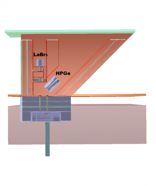
Two detectors | [[File:STMdetectors.png|500px|right|thumb|Two STM detectors in the STM Shielding House, the HPGe detector and the LaBr3 detector. ]] | ||
Two detectors are used to measure the X rays and gamma rays generated by the stopped muons. One of them, the LaBr3 detector (Lanthanum(III) bromide), is a 3-inch right-cylindrical cerium and strontium co-doped lanthanum bromide scintillating crystal detector, readout using a Hamamatsu R10233 PMT. | |||
It is capable of high rate operation up to and above 800 kcps with energy resolution 0.7%. The other, the HPGe (High Purity Germanium) detector, is a GMX70P4-95-AS Gamma-X HPGe Coaxial Detector It is capable of energy resolution of 0.1%, however its rate capability is limited to ∼70 kcps. | |||
Details of the detector geometries and materials can be found in docdb-49130. Details of the detector resolution can be found in docdb-36803. The energy resolution and full energy peak efficiency can be found in https://mu2ewiki.fnal.gov/wiki/STM_Detectors. | |||
=== Detector Response Simulation === | |||
The energy deposited by each photon in the HPGe detector is used to generate a waveform according to the deposited ionizing energy, measured gain, and collection efficiency. Waveforms from different photons are superimposed using the expected time and energy distribution.Electronic noise from the pre-amplifier and amplifier is added. The resulting waveforms are digitized using the 16bit ADC, and are used together to form STMWaveformDigis. | |||
A similar technique will be used for LaBr response. | |||
Latest revision as of 16:11, 3 July 2024
STM
Introduction of STM(Stopping Target Monitor)
The mu2e experiment measures [math]\displaystyle{ \mu^-Al\rightarrow e^-Al }[/math] process with a single event sensitivity,
[math]\displaystyle{ R_{\mu e} = \frac{Neutrinoless\ \mu\ to\ e\ conversion\ (CLVF)}{All\ \mu\ captured\ by\ Al\ nuclei\ at\ the\ stopping\ target } }[/math] or [math]\displaystyle{ R_{\mu e} = \frac{\varGamma (\mu^- + A(Z,N) \rightarrow e^- + A(Z,N)) }{\varGamma(\mu^- + A(Z,N) \rightarrow \nu _\mu + A(Z-1,N) ) } }[/math].
The goal of the STM is getting the number of stopped muons with 10% precision, so that the systematic error in the captured muon number is small enough compared with the statistical error in the number of muon-converted-electron.
Three transitions are utilized.
1) 347 keV, 2p-1s X-ray, 79.8% of muon stops. X-rays emitted when the muon comes to rest in the Stopping Target and is captured into atomic orbit (atomic capture). They are prompt signals with O(ps).
2)1809 keV gamma-ray, 51% of muon nuclear capture after muon stops. 61% of stopped muons are captured by the nuclei. These exhibit timing characteristics of the muonic lifetime ([math]\displaystyle{ \tau = 864 ns }[/math]).
3)844 keV gamma-ray 9.3% of muon nuclear capture after muon stops. The process leading to its emission is [math]\displaystyle{ \mu^- + ^{27}Al\rightarrow \nu _\mu + ^{27}Mg }[/math]. [math]\displaystyle{ ^{27}Mg }[/math] has a lifetime of 13.6 minutes. This line is appealing because of its time characteristics because it can be measured in the low background time during 1 second beam-off period in the 1.4 second main injector/recycler ring cycle.
Position and Shielding of STM
Because the strong radiation flash (consisting of muons, electrons, neutrons, X-rays and gamma-rays) overwhelms the electronic rate capability and causes radiation damages to detectors, the STM detectors need to be protected in several ways.
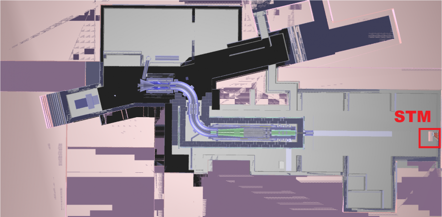
(1) STM is placed ~35 m away from the stopping target, not in the Detector Solenoid.
(2)A shielding house with small collimator apertures is built.
(3)Polyethylene absorbers are placed inside of the Detector Solenoid and in front of the HPGe detector.
STM Detectors
Detector Introduction
Two detectors are used to measure the X rays and gamma rays generated by the stopped muons. One of them, the LaBr3 detector (Lanthanum(III) bromide), is a 3-inch right-cylindrical cerium and strontium co-doped lanthanum bromide scintillating crystal detector, readout using a Hamamatsu R10233 PMT. It is capable of high rate operation up to and above 800 kcps with energy resolution 0.7%. The other, the HPGe (High Purity Germanium) detector, is a GMX70P4-95-AS Gamma-X HPGe Coaxial Detector It is capable of energy resolution of 0.1%, however its rate capability is limited to ∼70 kcps.
Details of the detector geometries and materials can be found in docdb-49130. Details of the detector resolution can be found in docdb-36803. The energy resolution and full energy peak efficiency can be found in https://mu2ewiki.fnal.gov/wiki/STM_Detectors.
Detector Response Simulation
The energy deposited by each photon in the HPGe detector is used to generate a waveform according to the deposited ionizing energy, measured gain, and collection efficiency. Waveforms from different photons are superimposed using the expected time and energy distribution.Electronic noise from the pre-amplifier and amplifier is added. The resulting waveforms are digitized using the 16bit ADC, and are used together to form STMWaveformDigis. A similar technique will be used for LaBr response.


