TransportSolenoidIntro: Difference between revisions
(Created page with "==Introduction and General Requirement== The Transport Solenoid consists of a series of wide aperture superconducting solenoid rings contained in two cryostats. Each cryostat...") |
No edit summary |
||
| (2 intermediate revisions by 2 users not shown) | |||
| Line 1: | Line 1: | ||
==Introduction | ==Introduction== | ||
The Transport Solenoid is responsible for transporting muons from where they are produced (from pion decays in the Production Solenoid) to where they can be captured in the Stopping Target. The captured muons are used to hunt for rare muon decays by the Mu2e experiment. The Solenoid is an S-shaped magnet, with a curvature that will only efficiently transport muons in the momentum range that have a high probability of stopping in our Stopping Target. The goal is not only to transport muons with high efficiency, but to also get rid of all particles that are not muons in this useful momentum range, to reduce the background flux of particles. | |||
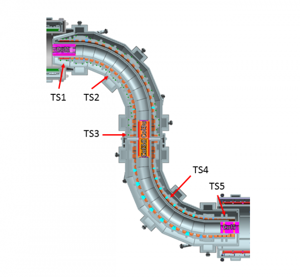
[[File:Transport solenoid.png|thumb|center|600px| Figure1.The Transport Solenoid with the significant components identified. ]] | |||
==General Requirements== | |||
The Transport Solenoid consists of a series of wide aperture superconducting solenoid rings contained in two cryostats. Each cryostat has a chimney for superconducting leads, helium supply and return lines and instrument ports. Internal mechanical supports in each cryostat transmit forces to external mechanical supports that connect to the experiment enclosure structure. The Transport Solenoid does not have an iron return yoke. | The Transport Solenoid consists of a series of wide aperture superconducting solenoid rings contained in two cryostats. Each cryostat has a chimney for superconducting leads, helium supply and return lines and instrument ports. Internal mechanical supports in each cryostat transmit forces to external mechanical supports that connect to the experiment enclosure structure. The Transport Solenoid does not have an iron return yoke. | ||
| Line 43: | Line 49: | ||
There is a gap between the TS3u and the TS3d coils as a result of the cryostat interfaces and the mechanical hardware necessary to actuate the rotating collimator and to insert the anti-proton window. To allow for a 220 mm gap, the inner radii of the TS3 coils have been increased to 465 mm, compared to inner radii of 405 mm for the remaining TS coils. Further details about the TSu design can be found in reference [2] | There is a gap between the TS3u and the TS3d coils as a result of the cryostat interfaces and the mechanical hardware necessary to actuate the rotating collimator and to insert the anti-proton window. To allow for a 220 mm gap, the inner radii of the TS3 coils have been increased to 465 mm, compared to inner radii of 405 mm for the remaining TS coils. Further details about the TSu design can be found in reference [2] | ||
[1] M. Lamm, “Transport Solenoid Requirements,” [http://mu2e-docdb.fnal.gov | [1] M. Lamm, “Transport Solenoid Requirements,” [http://mu2e-docdb.fnal.gov/cgi-bin/ShowDocument?docid=947 Mu2e-doc-947]<br> | ||
[2] G. Ambrosio et al., “TS123u Design Study”, [http://mu2e-docdb.fnal.gov | [2] G. Ambrosio et al., “TS123u Design Study”, [http://mu2e-docdb.fnal.gov/cgi-bin/ShowDocument?docid=2075 Mu2e-doc-2075] | ||
[[Category:Experiment]] | |||
[[Category:Tutorial]] | |||
Latest revision as of 01:59, 23 September 2022
Introduction
The Transport Solenoid is responsible for transporting muons from where they are produced (from pion decays in the Production Solenoid) to where they can be captured in the Stopping Target. The captured muons are used to hunt for rare muon decays by the Mu2e experiment. The Solenoid is an S-shaped magnet, with a curvature that will only efficiently transport muons in the momentum range that have a high probability of stopping in our Stopping Target. The goal is not only to transport muons with high efficiency, but to also get rid of all particles that are not muons in this useful momentum range, to reduce the background flux of particles.
General Requirements
The Transport Solenoid consists of a series of wide aperture superconducting solenoid rings contained in two cryostats. Each cryostat has a chimney for superconducting leads, helium supply and return lines and instrument ports. Internal mechanical supports in each cryostat transmit forces to external mechanical supports that connect to the experiment enclosure structure. The Transport Solenoid does not have an iron return yoke.
As shown in Figure 1, the Transport Solenoid is segmented into the following set of components:
- TS1 - Straight section that interfaces with the Production Solenoid.
- TS2 - Toroid section downstream of TS1.
- TS3 - Straight section downstream of TS2 TS3u coils are in the TSu cryostat and TS3d coils are in the TSd cryostat.
- TS4 - Toroid section downstream of TS3.
- TS5 - Straight section downstream of TS4 that interfaces with the Detector Solenoid.
The Transport Solenoid performs the following functions[1]:
- Pions and muons are created in the production target in the Production Solenoid. The Transport Solenoid maximizes the muon yield by efficiently focusing these secondary pions and subsequent secondary muons towards the stopping target located in the Detector Solenoid. High energy negatively charged particles, positively charged particles and line-of-sight neutral particles will be almost completely eliminated by the two 90° bends combined with a series of absorbers and collimators.
- The TS1 field must be merged with the field of the Production Solenoid at the interface for optimum beam transmission.
- There must be a negative axial gradient at all locations in the straight sections (TS1, TS3 and TS5) for radii smaller than 0.15 m to prevent particles from becoming trapped or losing longitudinal momentum.
- Through the first toroid section (TS2) the beam will disperse vertically, allowing a collimator in TS3 to filter the particles based on charge and momentum.
- The second toroid section (TS4) will nearly undo the vertical dispersion, placing the muon beam in the center of the TS5 axis.
- The TS5 field must be merged with the field of the Detector Solenoid at the interface for optimum transmission of the muon beam to the stopping target.
- The Transport Solenoid acts as a beamline interface for the antiproton window and various collimators, including the rotating collimator in TS3.
The Transport Solenoid consists of two independent cryostats and power units. The TS1, TS2 and TS3u coils are assigned to the TSu cryostat. The TS3d, TS4 and TS5 coils share the TSd cryostat. Each cryostat will have its own superconducting link, feed box, power converter and extraction circuit.
All TS coils use the same conductor design and similar cooling schemes. The TSu unit and the TSd unit are nearly identical, so only the preliminary design of TSu will be presented.
Tsu Design
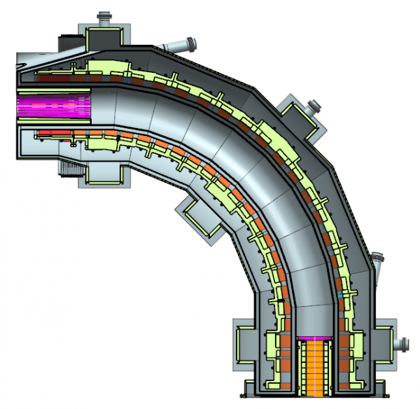
The TSu is shown in Figure2 and includes the following design features:
- A single cryostat is employed to avoid gaps between coils and reduce complexity and cost.
- The coils are powered in series to minimize the number of leads and the complexity of the power and quench protection systems.
- The quench protection strategy is based on extracting most of the energy and delivering it to external dump resistors.
- Coils are preassembled and tested inside modules, with two coils per module in most cases, in order to reduce complexity during cold mass assembly.
- The mechanical support system consists of 17 supports including: four supports along the toroid main radius, four axial supports close to each end, and three gravity supports.
There is a gap between the TS3u and the TS3d coils as a result of the cryostat interfaces and the mechanical hardware necessary to actuate the rotating collimator and to insert the anti-proton window. To allow for a 220 mm gap, the inner radii of the TS3 coils have been increased to 465 mm, compared to inner radii of 405 mm for the remaining TS coils. Further details about the TSu design can be found in reference [2]
[1] M. Lamm, “Transport Solenoid Requirements,” Mu2e-doc-947
[2] G. Ambrosio et al., “TS123u Design Study”, Mu2e-doc-2075

