CosmicRayVetoIntro: Difference between revisions
No edit summary |
No edit summary |
||
| (One intermediate revision by one other user not shown) | |||
| Line 1: | Line 1: | ||
==Introduction== | ==Introduction== | ||
A number of processes initiated by cosmic-ray muons can imitate the Mu2e signal. Such background events, which will occur at a rate of about one per day, must be suppressed in order to achieve the sensitivity required by Mu2e. Backgrounds induced by cosmic rays are reduced using shielding, which is placed both above and to the sides of the detector hall, as well as the shielding concrete surrounding the Detector Solenoid. These backgrounds are also reduced by particle identification criteria using the tracker and calorimeter, and by the Cosmic Ray Veto detector, whose purpose is to detect penetrating cosmic-ray muons. This detector encloses a significant portion of the Mu2e apparatus, as shown in the figure. When particles pass through, they are tracked, so that backgrounds consistent with cosmic rays are rejected as signal candidates. | |||
==General Requirements== | |||
The cosmic ray veto consists of four layers of long extruded scintillator strips, with aluminum absorbers between each layer. The nomenclature associated with the Cosmic Ray Veto is described in Table 1. The scintillator surrounds the top and sides of the Detector Solenoid (DS) and the downstream end of the Transport Solenoid (TSd), as shown in Figure 1 and Figure 2. The strips are 2.0 cm thick, providing ample light to allow a threshold to be set sufficiently high to suppress most of the backgrounds. Aluminum absorbers between the layers are designed to suppress punch through from electrons. The scintillation light is captured by embedded wavelength-shifting fibers, whose light is detected by silicon photomultipliers (SiPMs) at each end (except those counters closest to the TSd). A track stub consisting of at least three adjacent hit strips in different layers within a 5 ns time window signals the presence of a cosmic-ray muon. A conversion-like electron candidate within about 125 ns (exact duration to be optimized) of such a track stub is assumed to be produced by a cosmic-ray muon and is vetoed in the offline analysis. | The cosmic ray veto consists of four layers of long extruded scintillator strips, with aluminum absorbers between each layer. The nomenclature associated with the Cosmic Ray Veto is described in Table 1. The scintillator surrounds the top and sides of the Detector Solenoid (DS) and the downstream end of the Transport Solenoid (TSd), as shown in Figure 1 and Figure 2. The strips are 2.0 cm thick, providing ample light to allow a threshold to be set sufficiently high to suppress most of the backgrounds. Aluminum absorbers between the layers are designed to suppress punch through from electrons. The scintillation light is captured by embedded wavelength-shifting fibers, whose light is detected by silicon photomultipliers (SiPMs) at each end (except those counters closest to the TSd). A track stub consisting of at least three adjacent hit strips in different layers within a 5 ns time window signals the presence of a cosmic-ray muon. A conversion-like electron candidate within about 125 ns (exact duration to be optimized) of such a track stub is assumed to be produced by a cosmic-ray muon and is vetoed in the offline analysis. | ||
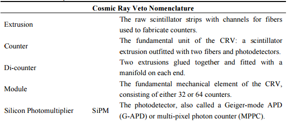
[[File:Crv table.png|thumb|center|600px|Table 1.Cosmic ray veto nomenclature. ]] | [[File:Crv table.png|thumb|center|600px|Table 1.Cosmic ray veto nomenclature. ]] | ||
| Line 31: | Line 30: | ||
The Mu2e collaboration has developed a complete set of requirements for the cosmic ray veto [1]. The outstanding technology-independent performance requirements of the cosmic ray veto are that it (1) limit the conversion-electron background to less than 0.1 events over the duration of the run; (2) produce cosmic-ray muon trigger primitives for detector calibration purposes; (3) produce less than 10% dead time; and (4) not use more than 20% of the DAQ bandwidth. | The Mu2e collaboration has developed a complete set of requirements for the cosmic ray veto [1]. The outstanding technology-independent performance requirements of the cosmic ray veto are that it (1) limit the conversion-electron background to less than 0.1 events over the duration of the run; (2) produce cosmic-ray muon trigger primitives for detector calibration purposes; (3) produce less than 10% dead time; and (4) not use more than 20% of the DAQ bandwidth. | ||
[1] E. Craig Dukes, “Mu2e Cosmic Ray Veto Requirements, “ [http://mu2e-docdb.fnal.gov | [1] E. Craig Dukes, “Mu2e Cosmic Ray Veto Requirements, “ [http://mu2e-docdb.fnal.gov/cgi-bin/ShowDocument?docid=944 Mu2e-doc-944] | ||
[[Category:Experiment]] | [[Category:Experiment]] | ||
[[Category:Tutorial]] | [[Category:Tutorial]] | ||
Latest revision as of 02:01, 23 September 2022
Introduction
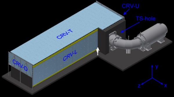
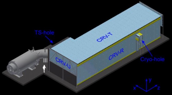
A number of processes initiated by cosmic-ray muons can imitate the Mu2e signal. Such background events, which will occur at a rate of about one per day, must be suppressed in order to achieve the sensitivity required by Mu2e. Backgrounds induced by cosmic rays are reduced using shielding, which is placed both above and to the sides of the detector hall, as well as the shielding concrete surrounding the Detector Solenoid. These backgrounds are also reduced by particle identification criteria using the tracker and calorimeter, and by the Cosmic Ray Veto detector, whose purpose is to detect penetrating cosmic-ray muons. This detector encloses a significant portion of the Mu2e apparatus, as shown in the figure. When particles pass through, they are tracked, so that backgrounds consistent with cosmic rays are rejected as signal candidates.
General Requirements
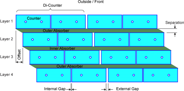
The cosmic ray veto consists of four layers of long extruded scintillator strips, with aluminum absorbers between each layer. The nomenclature associated with the Cosmic Ray Veto is described in Table 1. The scintillator surrounds the top and sides of the Detector Solenoid (DS) and the downstream end of the Transport Solenoid (TSd), as shown in Figure 1 and Figure 2. The strips are 2.0 cm thick, providing ample light to allow a threshold to be set sufficiently high to suppress most of the backgrounds. Aluminum absorbers between the layers are designed to suppress punch through from electrons. The scintillation light is captured by embedded wavelength-shifting fibers, whose light is detected by silicon photomultipliers (SiPMs) at each end (except those counters closest to the TSd). A track stub consisting of at least three adjacent hit strips in different layers within a 5 ns time window signals the presence of a cosmic-ray muon. A conversion-like electron candidate within about 125 ns (exact duration to be optimized) of such a track stub is assumed to be produced by a cosmic-ray muon and is vetoed in the offline analysis.
The cosmic ray veto must operate with an excellent efficiency, about 0.9999, in an intense radiation environment that consists of neutrons produced at the production target, stopping target, and muon beam stop, as well as gammas produced largely from neutron capture.
Unlike the other backgrounds to the Mu2e conversion signal, the cosmic-ray background scales as the detector live time. A direct measurement of the cosmic-ray background can and will be done when the beam is not being delivered. During normal beam operations, 16 times more cosmic-ray-muon induced conversion-like background events will be collected out-of-spill than will be collected in-spill.
As for the readout part. There are 2 WLF per scintillator, each fiber is readout at both ends with a SiPM - except for a few modules in the CRV-U region for which the radiation damage near TS3 is too severe for the SiPMs and so they are only readout at 1 end.
Requirements
The Mu2e collaboration has developed a complete set of requirements for the cosmic ray veto [1]. The outstanding technology-independent performance requirements of the cosmic ray veto are that it (1) limit the conversion-electron background to less than 0.1 events over the duration of the run; (2) produce cosmic-ray muon trigger primitives for detector calibration purposes; (3) produce less than 10% dead time; and (4) not use more than 20% of the DAQ bandwidth.
[1] E. Craig Dukes, “Mu2e Cosmic Ray Veto Requirements, “ Mu2e-doc-944


