TrackerIntro
Introduction
The Mu2e Tracker will precisely measure momentum of charged particles that traverse it. This is critical to distinguish the well-known momentum of the signal electrons from background particles that have different momenta. The momentum measurement can be made because a charged particle will trace a helical path through the uniform magnetic field of the Detector Solenoid and the radius of this helix is directly proportional to its momentum. The tracking chamber is designed to intercept this helical path, enabling the helix to be reconstructed and the radius to therefore be measured.
Requirements
The tracker must accurately and efficiently identify and measure 105MeV/c electrons while rejecting backgrounds and it must provide this functionality in a relatively unique environment. The tracker resides in the warm bore of a superconducting solenoid providing a uniform magnetic field of 1 Tesla1; the bore is evacuated to 10-4 Torr. A key feature of Mu2e is the use of a pulsed beam that allows for elimination of prompt backgrounds by looking only at tracks that arrive several hundred nanoseconds after the proton pulse. The tracker must survive a large flux of particles during the early burst of "beam flash" particles that result from the proton pulse striking the production target, but it does not need to take data during this time. The Mu2e signal window is defined as 700 < t <1695, where t = 0 is the arrival of the peak of the beam pulse at the stopping target. However, in order to study backgrounds such as radiative pion capture, the tracker must be fully efficient during the interval 500< t < 1700nsec; we take this as the tracker’s live window. To calibrate using positrons from π+→νe+ decays the tracker must also be able to collect data, during special runs with reduced beam intensity, for 300<t<1700 nsec.
Requirements for the tracker have been documented elsewhere [1] and are only summarized here.
The Detector Solenoid provides a uniform 1 Tesla field in the region occupied by the tracker. To have good acceptance for signal electrons without being overwhelmed by DIO electrons (including electrons scattered into the active region), the active area of the tracker extends from about 40 <r< 70 cm (where radius r is measured from center of the muon beam)1. Mechanical support, readout electronics, etc. are to be placed at r >70 cm, out of the way of both signal and DIO electrons. These dimensions depend on the size and geometry of the muon stopping target, the size of the muon beam, and the magnetic field properties; they have been optimized to maximize the acceptance to conversion electrons while minimizing the number of low energy electrons that intersect the tracker. The momentum resolution requirement is based on background rejection: the signal is sharply peaked, whereas backgrounds are broad (cosmic rays, radiative pion capture) or steeply falling (DIO electrons). For a Gaussian error distribution the requirement is that σ < 180 keV/c. This is simply a convenient reference point; the actual resolution is not Gaussian and may be asymmetric. Furthermore, scattering and straggling in material upstream of the tracker are significant contributors to the final resolution.
Mechanical Construction
The selected design for the Mu2e tracker is a low mass array of straw drift tubes aligned transverse to the axis of the Detector Solenoid, referred to as the T-tracker. The basic detector element is a 25 µm sense wire inside a 5 mm diameter tube made of 15 µm thick metalized Mylar®, referred to as a straw. This choice is based on several points.
- The straw can go from zero to 1 atmosphere pressure differential (for operating in a vacuum) without significant change in performance.
- Unlike other types of drift chambers, each sense wire is mechanically contained within a straw. Thus, failures remain isolated, improving reliability.
- The transverse design naturally places mechanical support, readout electronics, cooling, and gas distribution at large radii.
The detector has ~23,000 straws distributed into 20 measurement stations across a ~3 m length. Each station provides a ~200 µm measurementv of track position.
Each straw is instrumented on both sides with preamps and TDCs. Each straw has one ADC for dE/dx capability. The planned digitizer system is: 50 MHz, 12-bit ADC. To minimize penetrations into the vacuum, digitization is done at the detector with readout via optical fibers. Electronics at the detector will not require an external trigger: all data will be transferred out of the vacuum to the DAQ system, and a trigger may be implemented as part of the DAQ.
Straws
The T-tracker is made from 5 mm diameter straws, the assembly of which is shown in and Figure 1. Each straw is made of two layers of ~6 µm (25 gauge) Mylar®, spiral wound, with a ~3 µm layer of adhesive between layers, for a total wall thickness of 15 µm. The inner surface has 500 Å aluminum overlaid with 200 Å gold as the cathode layer. The outer surface has 500 Å of aluminum to act as additional electrostatic shielding and reduce the leak rate.

A 4.95 mm outer diameter brass tube is mechanically and electrically connected to each straw end using silver epoxy. Inside the brass tube is an extruded Kapton® tube to protect against breakdown at the edge of the brass tube. Inside the Kapton® tube is an injection molded plastic insert. Attached to a groove in the insert is a small, U-shaped brass pin. A 25 µm gold plated tungsten wire is soldered to the pin as well as epoxied to the plastic insert. Both brass parts are gold-plated to ensure good solder and epoxy joints.
Straw Assemblies
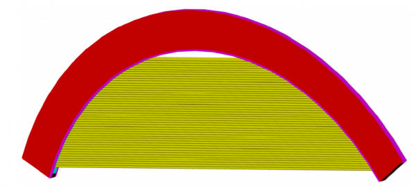
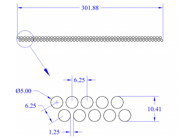
Groups of 96 straws are assembled into panels as shown in Figure 2. Each panel covers a 120° arc with two layers of straws, as shown in Figure 3. The double layer improves efficiency and helps determine on which side of the sense wire a track passes (the classic “left-right” ambiguity). A 1.25 mm gap is maintained between straws to allow for manufacturing tolerance and expansion due to gas pressure. This necessitates that individual straws be self-supporting across their span.
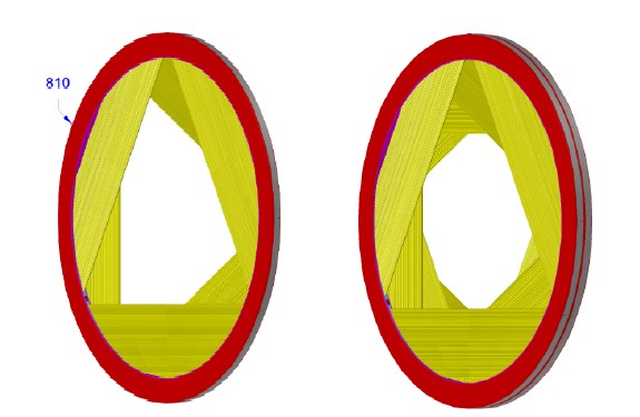
Six panels are assembled into a plane as shown in Figure 4. Three 120° panels complete the ring of one face; another three panels, rotated by 30°, complete another ring on the opposing face. After the plane is assembly, a cooling ring is attached around the outer diameter. This arrangement has been found to give the best stereo performance [4] and is chosen despite the mechanical complications compared with 60° rotation.
A pair of planes forms a station. The two planes are identical. During assembly the 2nd plane is rotated 180° around a vertical axis. The completed station is shown in Figure 4.
Tracker Frame
Eighteen stations are assembled into the completed tracker, shown in Figure 5. A breakdown of the number of components that make up the tracker (stations, planes, panels, etc.) is shown in Table 8.3. Horizontal beams maintain longitudinal alignment of the rings. The thicker ring seen at the upstream end, and the two thinner rings placed between stations at the downstream end, stiffen the structure. Stiffening rings and beams are stainless steel, pending further analysis and value engineering.
The entire tracker rests on four bearing blocks (not shown) placed near the horizontal beams and attached to the stiffening rings. The connection between the tracker and the bearing blocks are kinetic to avoid over-constraining and distorting the tracker frame, except all four points are constrained in the vertical direction (the frame is not rigid enough to support the weight without this). Vertical adjustment screws are included to level and center the frame.
Front End Electronics
To minimize penetrations through the cryostat, digitizers and zero-suppression logic are located on the detector. Requirements for the electronics [2] and DAQ system are documented separately. Here we summarize the implementation of on-chamber (front end) electronics. The flow of signals through the readout chain is shown in Figure 6.
The tracker uses “time division”: pulse timing is measured at each end of the straw in order to measure the position along the wire. The resolution is ~3cm; this is used for pattern recognition before using stereo for getting a more accurate position. Pulse height is measured to provide dE/dx for particle identification. Therefore each straw has:
- 2 preamp channels, 1 for each end.
- 2 TDC channels, 1 for each end.
- 1 ADC channel, measuring sum of both ends.
- 1 High voltage feed, with disconnect.
There are a total of 46,080 preamp and TDC channels, and 23,040 ADC channels.
[1] R. Bernstein, “Requirements Document for Mu2e Tracker,” Mu2e-doc-732 [2] A. Mukherjee, "Requirements for the Tracker Front-end Electronics", Mu2e-doc-3879


