ShieldingIntro
Inner Proton Absorber (IPA)
The purpose of the IPA is to reduce the rate of protons intercepting the tracker while minimizing energy loss and straggling of conversion electrons. The IPA should not intercept the muon beam. The IPA is a thin (0.5 mm thickness) conical frustum. It is required to be made of low-Z materials. Identifying a thin material that will hold the required shape is non-trivial, but it is expected that the requirements can be met using carbon fiber. Less expensive thermoplastic material such as HDPE is less likely to have sufficient mechanical rigidity at this thickness but the higher hydrogen content is preferred. The IPA will be supported from the OPA by tungsten wires. Three wires would support the IPA near its upstream end and another three wires would support it near its downstream end.
Based upon simulations [1], the preference is for an IPA with a uniform thickness. This can be achieved most effectively in designs in which the IPA is selfsupporting or requires only a minimal support structure, e.g. support wires. Carbon fiber can be made very stiff so it will satisfy the rigidity requirements. One issue associated with this option is that a mandrel is required on which to wind the carbon fibers. The cost of the mandrel would be a substantial fraction of the IPA manufacturing cost.
Assuming the IPA is realized in carbon fiber, it could be made at an internal facility at Fermilab. On the other hand, if the IPA is made of thermoplastics for considerations of cost or other reasons, it will be manufactured by an outside vendor.
Upstream External Shielding
The upstream external shielding of the Muon Beamline surrounds the Production Solenoid and isolates the primary proton beamline from the Detector Solenoid hall while shielding the Cosmic Ray Veto (CRV) from radiation generated at the production target located in the PS and resulting from the secondary beam transported by the upstream Transport Solenoid (TSu). The primary purpose of the Upstream External Shielding is to shield the Mu2e detectors, reducing the rate of neutron and gamma background impinging on the CRV to an acceptable level. This shielding also serves to isolate the primary proton beamline from the downstream muon beamline, dividing the lower level of the Mu2e Experiment Hall into two independent zones.
The current configuration of this shielding is composed of 138 tons of reinforced normal density concrete and 243 tons of reinforced higher density (barite) concrete. This concrete is supported by the lower level floor of the Mu2e Experiment Hall. The shielding as implemented in the current simulation is illustrated in Figure 1
Additional information on Fermilab experience with barite and barite concrete is summarized in [2].
Requirements
The Mu2e experiment will require a negative muon beam, stopping muons in an aluminum target and search for evidence of the neutrinoless conversion of stopped muons into electrons in the field of a nucleus [3]. During muon production, besides the required negatively charged muons, many other particles are created. The primary purpose of the TS magnets and collimator system is to perform charge and momentum selection on the particle flux exiting the PS. The S-shaped beamline is quite an effective filter of neutral particles however, to even further reduce the flux of particles headed downstream, additional shielding is required around the solenoid system. The amount and type of shielding required for the desired detector performance is dependent upon the configuration of other materials in the path of the emerging particles (such as the HRS [4]), as well as on the sensitivity of the particle detectors being shielded.
The primary purpose of the upstream external shielding around the PS and TSu is to reduce the rate of particles incident on the Mu2e detectors, and the requirements for the upstream external shielding are described in [5]. The rate incident upon the Cosmic Ray Veto must be suppressed to a low enough level to support efficient operation of the CRV, so that potential sources of background due to incident cosmic rays can be identified and suppressed by the CRV. The simulations have gone through numerous generations in an effort to arrive at a configuration that provides sufficient shielding capability implemented in (relatively) affordable materials. A recent version of results from the shielding simulation including CRV rates is available in [6]. The current understanding of the CRV rate requirements and results of implementing CRV detector response can be found in Chapter 10 and in [7], which also relies on parameters specified in [8]. An overview of the methods used to evaluate the CRV response is provided in [9]. An update on the most recent design of the shielding resulting from the simulations studies intended to match to the details of the civil construction plans is available in [10]. Simulations have illustrated the sensitivity of the CRV to significant gaps in coverage [11]. Efforts must be made to minimize open penetrations and direct line-of-sight cracks wherever feasible.
The upstream external shielding also isolates the primary proton beamline from the DS hall, providing a natural radiation zone break and serves as an element of the airflow control system for the Mu2e Experiment Hall.
The upstream external shielding is entirely external to the muon beamline. The temperature expected in this area is between 20 and 30 degrees Celsius (between 68 and 85 degrees Fahrenheit) [12]. Material must be dimensionally stable and maintain structural integrity over the operating life at these temperatures.
The reinforced concrete assemblies must be demonstrated to be stable under anticipated operating conditions, including the forces resulting from the solenoid fields. The design must also take into consideration appropriate seismic related constraints.
Technical Design
The upstream external shielding surrounds the upstream portion of the Mu2e muon beamline, isolating the primary beamline from the DS detector hall, reducing the particle flux on the Mu2e detectors. The upstream external shielding is composed of several elements as illustrated in Figure 1.
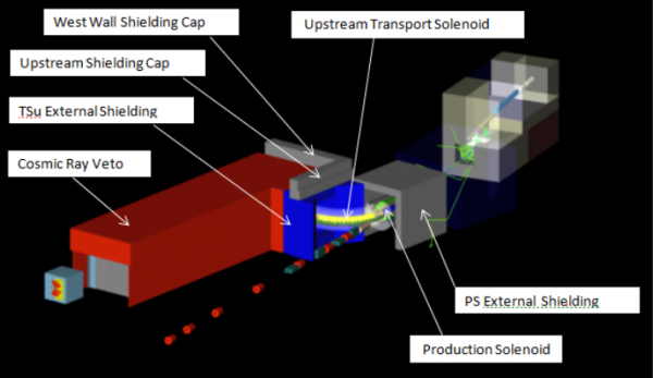
The PS External Shielding (shown in Figure 2) is currently composed of 22 inch thick reinforced concrete surrounding the sides and the top of the PS. The top of this shielding is 174 inches above floor level (Y), and the shielding is 207 inches long (Z), for a total mass of 90 tons. The cryo services to the PS penetrate this shielding in the south east corner just under the top of the shielding. An additional relief in this shielding may be required to accommodate the upstream muon beamline vacuum line.
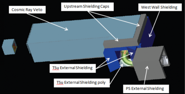
The TSu External Shielding is primarily high density (barite) concrete surrounding the downstream end of the TSu. The shielding is anticipated to be composed of 152 inch tall (Y) upright columns (shown triangular in profile in Figure 2 as per the current simulation), and 152 inch tall (Y) rectangular columns on each side of the TSu (for a total of 111 tons) and a high density concrete beam (39.5 inches wide (X), 23 inches tall (Y) and 264 inches long (Z), 15 tons) placed across the rectangular columns. In addition, there is currently a 24 inch wide (X), 132 inch tall (Y), and 15 inch long (Z) 3 ton barite concrete column in the north west corner between the PS External Shielding and the west TSu External Shielding column. This column is shorter than its neighbors to accommodate passage of services into the west wall relief. Note that the TSu services are routed near the ceiling, and pass above the PS external shielding.
The space below TSu between the TSu support stands is not yet fully defined and will likely be difficult to access. It is currently expected to be filled with perhaps 2 tons of poly beads (either bagged or retained via an aluminum or stainless steel frame), estimated at about half the density of poly and located approximately as indicated in Figure 2.
The West Wall Shielding completes the coverage of the relief in the west wall through which the cryo and vacuum services will be routed from the alcove below the Solenoid and Power Supply Room to the PS and TSu, and provides additional shielding of the Mu2e detectors from the radiation emerging from the primary proton target located in the PS. The West Wall Shielding is currently composed entirely of high density (barite) concrete, but based upon available simulation results, it is anticipated that perhaps some of this wall may eventually be shielded using normal density concrete. The west wall shielding is currently 264 inches long (X), 175 inches tall (Y), and 38.5 inches thick (Z), for a total of 113 tons. The precise dimensions of this West Wall Shielding must be revisited once the dimensions of the CRV and its support scheme have been finalized.
The Upstream Shielding Cap completes the isolation of the primary proton beam from the DS hall, and is composed of normal density concrete blocks placed on top of the TSu External Shielding (39.5 inches long (X), 56 inches tall (Y), and 262 inches thick (Z), for a total of 24 tons) and on top of the West Wall Shielding (262 inches long (X), 56 inches tall (Y), and 38.5 inches thick (Z), for a total of 24 tons).
The upstream external shielding is made primarily of concrete reinforced with steel bars. The Fermilab stock of blocks is unlikely to have sufficient quantity to fill the needs of the project. Furthermore, the stock blocks are unlikely to meet the challenging space constraints, so new blocks will need to be designed and procured. While the TSu external shielding columns implemented in the simulation (and shown in Figure 2) are composed of substantial blocks including unconventional (triangular) shapes, the actual implementation of the TSu external shielding is more likely to be realized utilizing an assembly of smaller blocks which are better matched to the lifting capacity available in the building. Figure 3. illustrates the details of the proposed implementation.
It is also anticipated that the alcove below the Solenoid and Power Supply Room may require shielding (to reduce backshine from the west wall relief).
Downstream External Shielding
Shielding needs to be placed around the downstream Transport Solenoid (TSd) and the DS to limit the number of neutrons and gammas reaching the Cosmic Ray Veto Counter. This shielding will be supported on the lower level floor of the Mu2e Experiment Hall. The primary purpose of this shielding is to reduce the rates of neutrons and gammas incident on the CRV to an acceptable level.
Requirements
The physics requirements for the downstream external shielding are aimed at facilitating detection of the experimental signature events by reducing the experimental background rates. In the Mu2e experimental setup the downstream cave is strategically placed to surround the TSd and DS cryostats. The end cap shielding encloses the downstream end of the muon beamline vacuum enclosure. The requirements for the downstream external shielding [13] are as follows:
- Reduce the neutron and gamma background incident upon the Cosmic Ray Veto (CRV) Counters.
- Allow a line of sight to the muon stopping target monitor and reduce the neutron and gamma background incident upon the muon stopping target monitor.
In addition to the above physics requirements, the downstream external shielding must satisfy the following mechanical and structural requirements:
- Provide a base for support of the CRV modules (as well as facilitate temporary storage of additional CRV modules removed from the upstream end during access to the antiproton window assembly at the TSu/TSd interface). The materials used in the downstream external shielding must therefore be able to withstand the loads imposed on them by other parts within the assembly as well as the loads of the CRV modules and associated mounting fixtures [14].
- Facilitate access to the IFB and the detector train inside the DS.
- Facilitate access to the antiproton stopping window assembly and the collimator rotation mechanism located at the TSu/TSd interface.
- Accommodate passage of power, cryo and vacuum services to the DS while reducing rates of particles escaping through this penetration
- Reduce rates of particles escaping through the TSd trench as appropriate.
- Reduce rates of particles escaping through the DS trenches as appropriate.
- Stay clear of the solenoids during installation, and satisfy the constraints imposed by the building geometry.
- Provide a relatively economical structure that is mechanically stable and serviceable while allowing for adequate exit pathways.
Material requirements depend upon a number of factors beyond the mass of the components, including forces induced by effects of the solenoid magnetic fields on the steel reinforcement bars [15], and capacity to temporarily store CRV modules on top of the shielding while accessing the antiproton window assembly at the TSu/TSd interface
Technical Design
The Downstream External Shielding is constructed of concrete and high density (barite) blocks, and will be completely external to the TSd and DS cryostats.
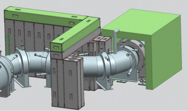
The current configuration of this shielding is primarily composed of reinforced concrete T blocks assembled into two independent (but mated) sections. The “Downstream Cave”, which surrounds the body of the TSd and DS, and the “End Cap Shielding”, which serves to enclose the downstream end of the muon beamline vacuum space. The fully assembled downstream external shielding is illustrated in Figure 4. The upstream open end of this shield will be placed against the downstream end of the TSu External Shielding [5].
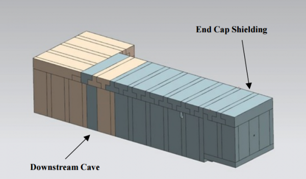
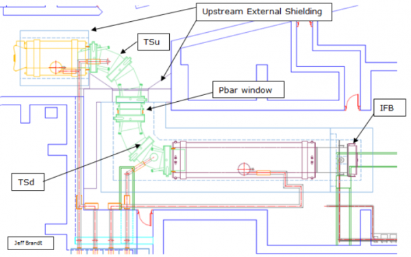
As described above and shown in Figure 5 below, the downstream cave is placed around the TSd and DS, and the end cap shielding surrounds the downstream end of the muon beamline vacuum enclosure. All downstream external shielding is supported independently of the DS.
The current design of the shielding requires 36-inch thick concrete to sufficiently suppress the rates at the CRV [9]. The upstream end of the downstream cave, which surrounds the TSd is composed of high density (barite) concrete [2]. The concrete blocks surrounding the muon stopping target region of the DS (~ 2m) are also to be composed of high density (barite) concrete, while the remainder of the concrete blocks are normal density concrete.
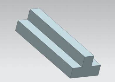
The downstream external shielding is constructed primarily of concrete blocks. The blocks include steel reinforcement bars and brackets. An illustration of a “typical” concrete block is shown in Figure 6
The concrete blocks include steel reinforcing bars and steel angles to protect the block’s edges (not shown in Figure 6). The default plan is to employ normal carbon steel reinforcement bars. Stainless steel reinforcement bars will only be used if demonstrated to be necessary due to magnetic field constraints. In an attempt to minimize line of sight cracks, the current plan is to assemble the downstream external shielding primarily from T blocks. Detailed drawings of similar T blocks are available at [16].
[1] MJ Lee, “Proton Absorber Optimization,” Mu2e-doc-3155
[2] Barite as a Shielding Alternative for the Anti-Proton Service Buildings Mu2e-doc-1334
[3] L. Bartoszek et al., “Mu2e Conceptual Design Report,” Mu2e-doc-1169
[4] V. Pronskikh, “Target Station: Heat & Radiation Shield, and its effect on neutron shielding,” Mu2e-doc-3099
L. Bartoszek et al., “Design of HRS-C,” Mu2e-doc-3025
L. Bartoszek, “Manufacturing Drawings for HRS-C,” Mu2e-doc-3926
[5] N. Andreev, “Requirements & Specifications WBS 5.4 – Upstream External Shielding,” Mu2e-doc-1044
[6] R. Coleman et al., “Geometry #13,” Mu2e-doc-3096
[7] Y. Oksuzian et al., “Studies of Neutron and Gamma Ray Radiation at the Mu2e Experiment and the Implications for the Cosmic Ray Veto Detector,” Mu2e-doc-3213
[8] C. Dukes et al., “Mu2e Cosmic Ray Veto Parameters,” Mu2e-doc-862
[9] Y. Oksuzian et al., “Background Rates in the Cosmic Ray Veto,” Mu2e-doc-3500
[10] R. Coleman, “Geometry 14---A Work in Progress…,” Mu2e-doc-3556
[11] R. Coleman, “Geometry 14---A Work in Progress…,” Mu2e-doc-3556
V1 slide 28 illustrates the consequences of a two inch gap between the bottom of the downstream external shielding and the floor.
[12] T. Lackowski, “Mu2e Conventional Facilities Requirements,” Mu2e-doc-1088
[13] R. Bossert and G. Ginther, “Requirements & Specifications --- WBS 5.9 Downstream External Shielding,” Mu2e-doc-1371
[14] E.C. Dukes, “Cosmic Ray Veto Parameters,” Mu2e-doc-862
[15] G. Gallo, M. Lopes and G. Moretti, “Estimate of the forces on support structures and other equipment located at the Mu2e experimental hall due to the stray magnetic field (using Magnetic Design Version 7),” Mu2e-doc-2444
and M. Lopes, “Mu2e Stray Field Mu2e,” Mu2e-doc-1381
and P. Ciacci, “Analysis of the Distortion of a Uniform Magnetic Field Caused by Magnetic Material,” Mu2e-doc-3374
[16] Type “T7.5” Shield Blocks, Fermilab engineering drawing 13-2-29 (CMTF) PC- 1; Type “T12 and T12P” Shield Blocks, Fermilab engineering drawing 13-2-29 (CMTF) PC-2.
