CalorimeterIntro
Introduction
The Mu2e calorimeter is vitally important in reducing backgrounds. Its primary purpose is to provide a set of measurements that complement the information from the tracker and enable us to reject backgrounds due to reconstruction errors and cosmic ray interactions not vetoed by the cosmic ray veto. The energy resolution of the calorimeter complements, but is not competitive with, that of the tracking detector. Even a coarse confirmation of track energy by the calorimeter will, however, help reject backgrounds from spurious combinations of hits from lower energy particles. For real tracks, activity in the tracker and in the calorimeter will be correlated in time. The combination of these two timing measurements provides a time-of-flight system that could be capable of providing particle identification information.
Requirements
The design of the Mu2e detector is driven by the need to reject backgrounds to a level consistent with a single event sensitivity for μ → e conversion of the order of 3 × 10-17. The calorimeter system is a vital link in the chain of background defenses. A background of particular concern is false tracks arising from pattern recognition errors that result from high rates of hits in the tracker. The accidental hits could combine with, or obscure, hits from lower energy particles, to create a trajectory consistent with a higher energy conversion electron. Thus a primary purpose of the Mu2e calorimeter is to provide a second set of measurements that complement the information from the tracker and enable us to reject background due to reconstruction errors. Another source of background is cosmic ray muons, not vetoed by the CRV system, that stop in the calorimeter and produce a backward-going electron track within the 105 MeV acceptance window. A calorimeter with excellent time resolution can reject such tracks.
The energy resolution of a crystal calorimeter complements, but is not competitive with, that of a tracking detector. Even a coarse confirmation of track energy by the calorimeter will, however, help reject backgrounds from spurious combinations of hits from lower energy particles.
For real tracks, activity in the tracker and in the calorimeter will be correlated in time. The time resolution of the calorimeter should be comparable to the time resolution of extrapolated tracks from the tracker, estimated to be of ~1 nanosecond. A calorimeter timing resolution of < 1 ns is consistent with the tracker and can be easily achieved.
The requirements for the calorimeter have been documented by the Mu2e collaboration [1]. The primary functions are to provide energy, position and timing information to confirm that events reconstructed by the tracker are well measured and are not the result of a spurious combination of hits. Moreover, the calorimeter should also provide the experiment’s trigger. This leads to the following requirements:
- An energy resolution of about 5% at 100 MeV is desirable to confirm the electron momentum measurement from the tracker, which is much more precise.
- A timing resolution better than ~ 0.5 ns is required to ensure that energy deposits in the calorimeter are in time with events reconstructed in the tracker.
- A position resolution better than 1 cm is necessary to allow comparison of the position of the energy deposit to the extrapolated trajectory of a reconstructed track.
- The calorimeter should provide additional information that can be combined with information from the tracker to distinguish muons from electrons.
- The calorimeter shall be utilized in the trigger to identify events with significant energy deposits.
The energy resolution of a crystal calorimeter complements, but is not competitive with, that of the tracking detector. Even a coarse confirmation of track energy by the calorimeter will, however, help reject backgrounds from spurious combinations of hits from lower energy particles.
Design Concept
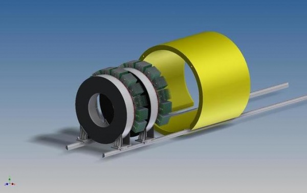
In the 100 MeV energy regime, a total absorption calorimeter employing a homogeneous continuous medium is required to meet the resolution requirement. This could be either a liquid such as xenon, or a scintillating crystal; we have chosen the latter. The baseline design selected for the Mu2e calorimeter uses array of CsI crystals arranged in two annular disks. Electrons following helical trajectories spiral into the front faces of the crystals, as shown in Figure 1. Photo-detectors, electronics and services are mounted on the rear face of the disks. The crystals are of square shape; there are a total of 674 crystals. Each crystal is read out by two large-area APDs; solid- state photo detectors are required because the calorimeter resides in a 1 T magnetic field. Front-end electronics is mounted on the rear of each disk, while voltage distribution, slow controls and digitizer electronics are mounted behind each disk. A laser flasher system provides light to each crystal for relative calibration and monitoring purposes. A circulating liquid radioactive source system provides absolute calibration and an energy scale. The crystals are supported by a lightweight carbon fiber support structure.
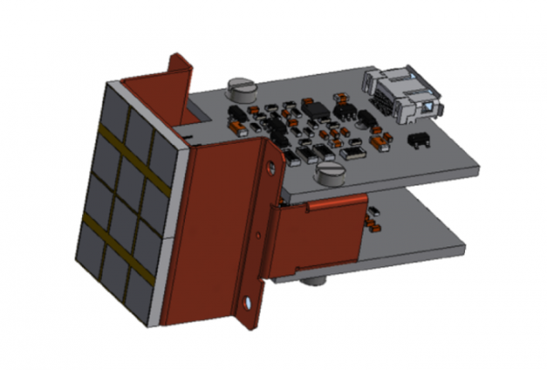
The CsI crystals readout is done by UV-extended silicon photomultipliers (SiPMs). The requirement of having a small air gap between crystal and photodetector and the request of redundancy in the readout implies the use of custom devices. For the Mu2e experiment we have increased the transversal dimension of the CsI from (30 × 30) to (34 × 34) mm2 in order to accomodate two (2 × 3) arrays of 6 × 6 mm2 UV-extended SiPM. The samples already procured show a good PDE (∼ 30% at 315 nm) with a gain greater than 106 at the operation voltage.
Each SiPM is directly connected to the readout electronics (Figure 2) and to a dedicated board housing a transimpedence preamplifier with a settable gain ×15 or ×30, 2 V dynamic range and 15 ns rise time. This digital boards are housed into 11 crates (in the top of each disk) per disk with 20 differential channels per board. These boards are composed by a mezzanine board for input of SIPM signals and HV setting and a Waveform Digitizer section based on SmartFusione II FPGA with 200 Msps 12 bit ADC.
[1]R. Bernstein, D. G. Hitlin, S. Miscetti, “Calorimeter Requirements,” Mu2e-doc-864 (04/08/2016).

