MuonBeamlineIntro
Introduction
The fundamental goals of the muon beamline are to deliver a stopped muon rate of approximately 10^(10) per second to the muon stopping target, located in the Detector Solenoid (DS), and to reduce the background in the tracker, calorimeter and cosmic ray veto detectors to a level sufficient to achieve the desired experimental sensitivity. It is important to identify all possible background sources and equip the muon beamline vacuum space with elements that can produce a muon beam with the requisite cleanliness while guiding negatively charged muons to the stopping target. The stopping target and the surrounding absorbers must be designed to maximize the capture of muons and transmission of conversion electrons to the detector while minimizing particles that can result in background.
General Requirements
The muon beamline is essentially a vacuum space, which serves as a free path for negatively charged muons within the desired momentum range. The muons spiral to the detector area along the streamline of the B-field (created by superconducting solenoid magnets). The S-shaped Transport Solenoid muon channel is surrounded with coils that form a toroidal B-field in the two curved sections and solenoidal fields in the three straight sections. The upstream toroidal field, with strategically placed collimators and absorber, filters the particle flux producing a momentum- and charge-selected muon beam, with good reduction in contamination from charged particles: e ± , µ+ , π± , p and neutral particles. A thin window resides in the central straight section of the muon beamline. The window stops antiprotons from reaching the muon stopping target and creating background. It also serves to separate the upstream and downstream muon beamline vacuum volumes to prevent radioactive ions or atoms from the production target from contaminating the detector solenoid volume. The muon stopping target consists of thin aluminum discs placed in the graded magnetic field region of the Detector Solenoid warm bore. The muons have a high probability of stopping in the muon stopping target. Muons not stopped in the target mostly bypass the detectors and are transported to the muon beam stop. Protons and neutrons originating from the muon capture process in the stopping target, final collimator and muon beam stop are attenuated by absorbers to minimize detector background rates. Stray particles produced in the vicinity of the primary production target and muon beamline are suppressed from impacting the cosmic ray veto detectors by substantial shielding surrounding the muon beamline.
The muon beamline Level 2 system is responsible for a variety of items essential to the effective transmission of the muon beam and performance of the Mu2e detectors. Muon beamline (WBS 5) is subdivided into eleven Level 3 sub-projects:
- WBS 5.1 Muon Beamline Project Management
- WBS 5.2 Muon Beamline Vacuum System
- The end enclosures and the infrastructure to evacuate the upstream and downstream muon beamline
- WBS 5.3 Muon Beamline Collimator
- The collimators and antiproton absorbers that reside inside the bore of the Transport Solenoids
- WBS 5.4 Upstream External Shielding
- The muon beamline shielding external to the Production Solenoid (PS) and the Upstream Transport Solenoid (TSu)
- WBS 5.5 Muon Stopping Target
- The muon stopping target and its support frame
- WBS 5.6 Muon Stopping Target Monitor
- The muon stopping target monitor and associated infrastructure
- WBS 5.7 Detector Solenoid Internal Shielding
- Shielding internal to the Detector Solenoid (DS) primarily intended to reduce background rates incident upon the tracker and calorimeter.
- WBS 5.8 Muon Beam Stop
- Muon beam stop and supports
- WBS 5.9 Downstream External Shielding
- The muon beamline shielding external to the Downstream Transport Solenoid (TSd) and the Detector Solenoid (DS).
- WBS 5.10 Detector Support and Installation System
- The system designed to support the assembled detector train, including the muon stopping target, the DS Internal Shielding, tracker, calorimeter and muon beam stop. This system will facilitate relative alignment of the detectors, insertion into the DS bore, and extraction from the DS bore for detector servicing when required.
- WBS 5.11 Muon Beamline System Integration
The muon beamline WBS dictionary defines the technical objectives, scope, deliverables, relationships and assumptions for these various efforts [1]. The following sections provide a summary of the requirements and technical design for the muon beamline elements. Interfaces with the other Level 2 subsystems are documented in [2].
Vacuum System
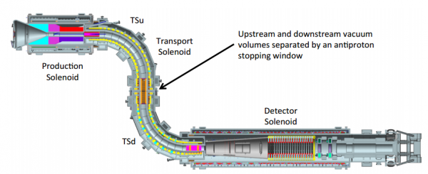
The muon beamline vacuum system consists of two distinct vacuum volumes that are physically separated by a sealed vacuum window located between sections of the Transport Solenoids as indicated in Figure 1.
This vacuum window also serves as an antiproton stopping window [3]. (Additional details can be found in Section 7.3.) The upstream vacuum volume is defined by the stainless steel inner cryostat wall of the Production Solenoid, the Heat and Radiation Shield (HRS), plus the stainless steel inner cryostat wall of the upstream Transport Solenoid (TSu). For convenience we denote this space as PS+TSu. The downstream vacuum volume is defined by the stainless steel inner cryostat walls of the downstream portion of the TS (TSd), and the Detector Solenoid (DS). For convenience we denote this space as TSd+DS.
Under normal operating conditions, the operating pressure shall be maintained at or below the required vacuum levels listed below. The pressure in the PS+TSu is set by target lifetime criteria. The requirement on the pressure in the TSd+DS is intended to minimize secondary interaction in the detector volume. The time required to pump down from one atmosphere to the required pressure in both the upstream and downstream vacuum volumes is expected to be on the order of one week.
Both vacuum volumes will need to be prepared and cleaned using standard high vacuum cleaning practices in order to achieve the required vacuum levels. However, neither the PS+TSu nor the TSd+DS have stringent operational cleanliness requirements. That means that minor oil contamination from the vacuum pumps will be acceptable. These volumes do not require accelerator quality vacuums or integrated silicon chip manufacturing cleanliness standards in operation.
A performance analysis of the muon beamline vacuum system is provided in TDR Section 7.2.2. High vacuum pumps used for the PS + TSu volume will be located in magnetic fields on the order of 500 Gauss. There is little concern that the magnetic field in the PS region will be adversely affected by magnetic material in the vacuum pumps located in the remote handling room. Therefore, these pumps and associated valves and instrumentation do not need to be non-magnetic as long as the equipment can function in those fringe fields and magnetically induced mechanical forces on those objects can be addressed. Because the pumps used for the PS + TSu volume will be located several meters from the PS vessel, the pumping speed (and therefore the ultimate system pressure) is greatly affected the line diameter and length. This line will need to be at least 0.6 meter in diameter.
Gas load contributions due to material outgassing, permeation across the vacuum boundary, leaks from the multiple vacuum windows, leaks from the many feed-throughs in the vacuum enclosures, and leaks from the detector straw tubes have been estimated and used to size the high vacuum pumps. Bake-out of the assembled vacuum system components is impractical. Therefore, outgassing rates used in this assessment are based on minimally cleaned, non-baked surfaces.
Requirements
The requirements for the muon beamline vacuum system are provided in [4] and can be summarized as follows:
- Required vacuum level:
PS + TSu; ≤ 1 x 10⁻⁵ torr
DS + TSd; ≤ 1 x 10⁻⁴ torr - Required vacuum pump down time:
PS + TSu; approximately 100 hours
DS + TSd; approximately 100 hours - Magnetic field anticipated in vicinity of high vacuum pumps:
PS + TSu; approximately 500 Gauss
DS + TSd; approximately 600 Gauss - Magnetic field anticipated in vicinity of backing and roughing vacuum pumps:
PS + TSu; approximately 100 Gauss
DS + TSd; approximately 100 Gauss - Required pre-operational cleanliness for vessels:
PS + TSu; standard high vacuum cleaning and degreasing
DS + TSd; standard high vacuum cleaning and degreasing - Required operational cleanliness:
PS + TSu; minimize, but not eliminate vacuum pump oil back-streaming
DS + TSd; minimize, but not eliminate vacuum pump oil back-streaming - Appropriate windows and access ports must be provided as part of the enclosure for the Production Solenoid
- Appropriate window, ports and feedthroughs must be provided as part of the enclosure for the Detector Solenoid
- Vacuum lines (and other services) should be located to minimize penetrations in the detector shielding
- Penetrations to the transport and detector solenoids should if at all possible come through the bottom, and if they cannot be through the bottom, then they should be away from the target region. In no cases should they penetrate the top [5].
Few, if any components of the vacuum system will be ASME code stamped since the ASME code applies to pressure vessels designed with an internal pressure of at least 15 psig. The Mu2e vacuum vessels will not be designed for such a high internal pressure. However, the external pressure criteria in the ASME Boiler and Pressure Vessel Code Section VIII, Division 1 will be applied to the vacuum vessels to ensure the vacuum vessels will not collapse. Applying the external pressure portions of the ASME pressure vessel code to the vacuum vessels is in accordance with the standards of the Fermilab Engineering Manual [6] and Fermilab ES&H Manual (FESHM) [7], particularly the Vacuum Vessel Safety chapter 5033 [8]. Some welding details critical to good vacuum practice (avoiding trapped volumes) do not meet the ASME code requirements for pressure vessels and therefore preclude code stamping of the vacuum vessels. Vacuum windows (thin membrane used for allowing the beam to enter the vessels, not optical windows) will meet FESHM chapter 5033.1 – Vacuum Window Safety [9].
An appropriately sized relief valve will be required on each vacuum volume to prevent the volume from being pressurized.
Muon Beamline Collimators
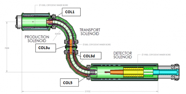
The muon beamline collimators, in conjunction with the Transport Solenoids, will maximize the transport of negative muons that stop in the stopping target in the Detector Solenoid (DS) and strongly suppress all other particles delivered to the DS. As illustrated in Figure 2, there are four collimators located within the warm bore of the muon beamline transport solenoids.
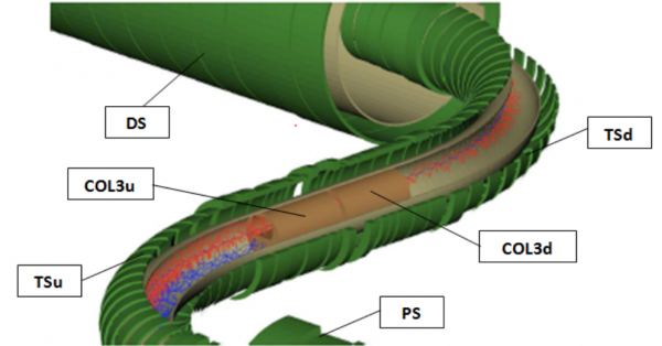
The muon beamline collimators filter the beam as it passes through the Transport Solenoids (TSu and TSd), selecting muons of the desired charge and momentum range to optimize the probability of their capture in the muon stopping target. This selection is achieved by a vertical offset of the apertures in the two collimators (COL3u and COL3d) with respect to the horizontal center plane to take advantage of “curvature drift” in the two transport solenoid bends formed by the two toroidal sections (see Figure 3). In this curved B-field negatively charged particles are deflected upward in the first curved section, and pass through the offset apertures in COL3u and COL3d, and are deflected back onto the nominal beam line in the second curved section [10][11]. Since the drift direction depends on the charge, positively charged particles are driven downward in the first curved section and stopped in COL3u and COL3d. The extent of a particle’s vertical displacement at the TSu/TSd interface is momentum dependent, thus the size and location of the vertical aperture will also select the beam by momentum. COL3u and COL3d are designed so that they can be rotated on demand to efficiently transport positive muons in that rotated configuration to facilitate the collection of detector calibration data.
In addition to the role of beam filter the upstream collimator, COL1, protects the first several TS coils from radiation originating in the production target.
The detector area is required to be shielded from neutron background. This is the primary purpose for introducing COL5 in the Mu2e muon beamline and as seen in Figure 2, COL5 is located near the upstream end of the DS.
A thin window assembly is installed between COL3u and COL3d to absorb antiprotons in the beam and to separate the muon beamline vacuum space into independent upstream and downstream volume. More recent studies have indicated that an additional thin absorber will also be required to sufficiently suppress backgrounds from high energy antiprotons [12]. This window is proposed to be mounted near the upstream end of COL1, and is referred to here as the COL1 antiproton window.
Requirements
The Mu2e system of collimators, in conjunction with the TS magnet system, will maximize the transport of negative muons that stop in the stopping target in the Detector Solenoid (DS) and strongly suppress all other particles delivered to the DS. As described in [13], the collimators and the antiproton stopping windows are required to:
- Charge and momentum select particles, preferentially muons from the beam
- Absorb antiprotons at the stopping windows
- Inhibit migration of radioactive molecules downstream into the detector solenoid
- Protect the detectors from neutron background and low momentum muons which might not hit the stopping target
- Reduce particle debris incident upon TSu originated from the production target
The primary purpose of the collimators is to select charge and momentum by exploiting the drift, perpendicular to the plane of the S-shaped TS magnet, in opposite directions by positive and negative charges. In the upstream curved solenoid portion, as shown in Figure 3, the spiraling positive (blue) and negative (red) muons are deflected downwards and upwards respectively, by amounts that depend on their momentum. The vertical displacement midway through the S-shape TS magnet is:
where: e is the magnitude of the charge of the electron, and PL (PT) is the component of the momentum along s(transverse) the magnetic field. The particles also execute fast gyrations with radius:
Using the above equations the collimators can be designed to filter the beam favoring low-momentum particles. The collimators need to be optimized to remove or heavily suppress electrons above 100 MeV. By using rotatable collimators (COL3u and COL3d) with offset apertures the selection cited above can be achieved. These collimators will allow passage of the low momentum negative particles, including the desired low momentum negative (or positive – if the collimators are rotated 180 degrees) muons and strongly suppress positives (or negatives). The particle trajectories are re-centered on the solenoid axis by the second curved section of the TS.
Antiprotons (p-bar), if allowed to continue on to the muon stopping target, would produce a serious physics background [14]. There are several ways to decrease p-bar induced backgrounds. The Mu2e approach is to introduce thin windows in the transport solenoid region. The windows need to be thick enough to reduce the probability for p-bar passage through the windows but also thin enough to not substantially decrease the muon yield. Secondary particles emerging from the antiproton windows need to be filtered out. These requirements will drive the locations and sizes of the antiproton windows. The antiproton windows should not be placed further downstream than the TSu/TSd interface. Requiring an antiproton window near the upstream end of COL1 and at TSu/TSd interface sandwiched between COL3u and COL3d will satisfy the above requirements [12].
Radioactive molecules will be generated in the production solenoid area. These molecules can be long-lived and with time they can migrate downstream to the detector area producing undesirable physics background. To prevent this migration the upstream PS+TSu vacuum volume will be isolated from the downstream TSd+DS vacuum volume by the antiproton stopping window assembly at the TSu/TSd interface, which will be a vacuum tight separator as well. This vacuum window assembly needs to suppress molecule diffusion through the window material.
Antiproton windows
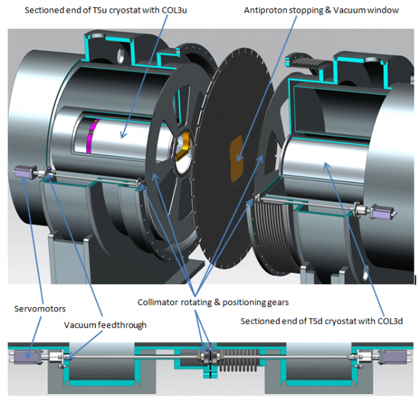
The anti-proton stopping window assembly positioned between COL3u and COL3d is shown in Figure 4. The profile of that window was optimized in a study reported in [3]. As cited above, an additional thin absorber to be mounted near the upstream end of COL1 will also be required to sufficiently suppress backgrounds from high energy antiprotons [12].
The thin window at the TSu/TSd interface is currently specified as a beryllium plate whose thickness is 200µm below the nominal aperture (with the collimators oriented to transport negative beam). The thickness of the window increases to a maximum of 1301µm above the top of the collimator aperture [12]. This beryllium window will be installed in the center of the stainless steel support disc (see Figure 4). Vacuum tight seals of the window are provided by a flange. The operating pressure inside the bore upstream of the antiproton stopping window assembly at the TSu/TSd interface is specified to be 10-5 torr [4]. Downstream of that antiproton stopping window assembly the operating pressure is specified to be 10-4 torr [4].
The version of the COL1 antiproton absorber, as represented in the most recent simulations [12], is a 350 µm thick kapton window. This window is centered on the muon beamline and positioned just 1mm upstream of COL1. The diameter of this window is 30cm. Due to the radiation levels expected in this region, a more robust material should be adopted in the final configuration. Aluminum and beryllium are candidates for the window material. The 1mm gap is also likely to be modified since it serves to baffle the pump down of the TSu region.
[1] G. Ginther, “Muon Beamline WBS Dictionary,” Mu2e-doc-991
[2] G. Ginther, “Mu2e Muon Beamline Interface Specification,” Mu2e-doc-1168
[3] J. Miller, “Pbar Window Geometry Update,” Mu2e-doc-3179
E. Barnes, J. Miller, S. Stroganov, and V. Khalatian, “Pbar simulations as a function of Be window thickness and changes to TS1,” Mu2e-doc-1942
[4] D. Pushka, “Requirements for Muon Beamline Vacuum system, WBS 5.2,” Mu2e-doc-1481
[5] E.C. Dukes, “Cosmic Ray Veto Requirements,” Mu2e-doc-944
[6] Fermilab Engineering Manual
[7] Fermilab ES&H Manual (FESHM)
[8] Fermilab ES&H Manual Chapter 5033 – Vacuum Vessel Safety
[9] Fermilab ES&H Manual Chapter 5033.1 – Vacuum Window Safety
[10] M. L. Lopes et al., “Studies on the Magnetic Center of the Mu2e Solenoid System,” IEEE Transactions on Applies Superconductivity, Vol 24, No, 3, June 2014 4100605
[11] M. Lopes, “Magnetic Requirements: What are they and how do we fulfill them?,” Mu2e-doc-3942
[12] Z. You, “Antiproton Background in Mu2e”, Mu2e-doc-4139
[13] ] N. Andreev, “Requirements & Specifications WBS 5.3 – Muon Beamline Collimators,” Mu2e-doc-1044
[14] J. Miller, “Requirements Document: Anti-Proton Window,” Mu2e-doc-941


