ProductionSolenoidIntro
Introduction
The Production Solenoid surrounds the Production Target, where proton interactions create cascades of particles. The job of the Production Solenoid is to collect and focus low energy pions that are created in these interactions using a gradient magnetic field. Pions decay to muons 99% of the time. The more pions that the Production Solenoid delivers to the Transport Solenoid, the more muons the experiment will have with which to search for rare muon decays.
Further Information
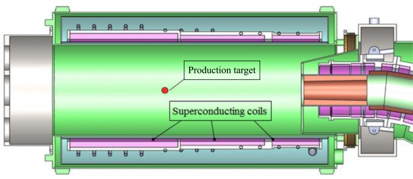
The Production Solenoid (PS), shown in Figure 1. The role of PS is to collect and focus pions and muons generated in interactions of the 8-GeV proton beam with a tilted high-Z target (tungsten) by supplying a peak axial field between 4.6 T and 5.0 T and an axial gradient of ~1 T/m within the 1.5 m diameter warm bore.
The PS is a challenging magnet because of the relatively high magnetic field and a harsh radiation environment that requires state-of-the-art conductor both in terms of the current-carrying capacity and structural strength. The PS coils are protected from radiation by a massive Heat and Radiation Shield (HRS) made of bronze, placed within the warm magnet bore. The HRS volume and cost were minimized while keeping the absorbed dose, peak power density, total power dissipation and number of displacements per atom (DPA) within the acceptable limits.
The magnet consists of three superconducting coils made of Al-stabilized NbTi cable surrounded by support shells made of structural Al and bolted together to form a single cold-mass assembly. The cold mass is supported inside the cryostat using a system of axial and radial support rods. During normal operation of the Mu2e magnet system, the axial force on the cold mass is about 1.3 MN acting toward the TS. The axial force reverses the direction in the case of a quench during stand-alone PS operation, which requires a 2-way axial support system.
In the case of a quench, the quench protection system extracts the stored energy to a dump resistor located outside of the magnet cryostat. Because of the relatively low resistivity of the Al support shells, a considerable fraction of the stored energy dissipates there due to eddy currents, accelerating the quench propagation in the coil volume.
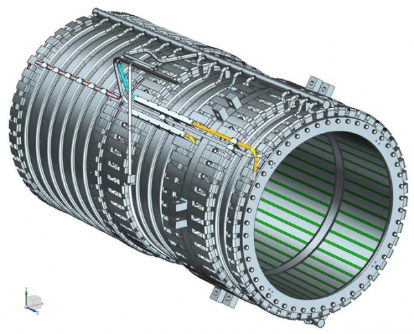
The cold mass as shown in Figure2 is instrumented with voltage taps, temperature gauges, strain gauges, and displacement sensors that monitor the magnet parameters during operation. Witness samples made of Al and Cu are placed at strategic locations on the inner cold mass surface to monitor the degradation of the cable stabilizer under irradiation. Once the critical level of degradation is detected, the magnet will be thermo-cycled to room temperature to restore the stabilizer resistivity.
The production solenoid does not have an iron return yoke.
Requirements
The Mu2e Production Solenoid (PS) magnet must meet the specific design and operational requirements as defined in [1]. Because of the relatively high cost, complexity and difficulty to replace once installed into the system, the PS should have adequate operating margins and be as fail-resistant as practically achievable.
In particular, the magnet must be able to operate with the other adjacent magnets or standalone, survive the worst-case quench, tolerate reversal of the axial force direction, and return to the nominal operating parameters without retraining after each thermal cycle. The main magnet requirements to be used as the design key point are discussed below.
- Magnetic Field
The magnetic field requirements for the Mu2e experiment are described in [2]. The PS field varies with the axial position. The maximum axial field on the axis is required to be at least 4.5 T. The axial field shall monotonically decrease with no more than ±5% non- linearity from the peak value to 2.5 T over the length of 2.8 m. In order to guarantee meeting the peak field requirement, the magnet shall be designed and fully operational at the maximum axial field of 5.0 T while meeting all other requirements under the static thermal load, excluding the particle radiation load. Note that energizing the magnet to 5.0 T requires using a trim power supply in TS to maintain the 2.5 T field at the interface with the TS magnet.
- Particle Radiation Load
The magnet will experience particle irradiation due to interaction of the proton beam with the fixed target in the magnet aperture. The HRS is designed to limit the main radiation quantities to the following values: peak coil power density - 30 μW/g, total heat load on the cold mass - 100 W, peak lifetime absorbed dose - 7 MGy, and displacements per atom - (DPA) – (4-6)•10-5 year-1 [3]. The magnet shall be designed to operate under this maximum radiation load while meeting all other requirements.
- Degradation of RRR
The residual resistivity ratio (RRR) of the cable stabilizer degrades under irradiation at cryogenic temperatures. The minimum allowable values for the RRR of Al and Cu stabilizers are 100 and 50, which will be reached in about a year of continuous operation for the given DPA values with a sufficient safety margin [3]. Once the critical degradation of RRR is detected, the magnet will be thermo-cycled to recover the RRR. The magnet shall be designed to operate at the minimum allowable values of RRR while meeting all other requirements.
- Cooling
The magnet shall be cooled by heat conduction to the thermo-siphon system connected to the cryogenic plant, which provides the nominal liquid helium temperature of 4.70 K. In order to maintain the required 1.5 K temperature margin, the maximum allowable temperature of the superconducting coils is 5.10 K when operating at 4.6 T peak axial field and 4.85 K when operating at 5.0 T peak axial field.
- Quench Protection
The magnet will be protected from quenches by an active quench protection system, which continuously monitors the coil voltages and extracts the energy to an external dump resistor once a quench is detected. The maximum coil temperatures and voltages during a protected quench must be limited to 130 K and 600 V.
- Structural Criteria
The superconducting coils shall be reinforced against Lorentz forces by external support shells made of structural Al, and the cryostat shells will be made of austenitic stainless steel. The thicknesses of the coil support shells and cryostat shells must be chosen according to the 2013 ASME Boiler and Pressure Vessel Code for operation at 5.0 T peak axial field. Plastic deformation of the cable stabilizer shall be considered during calculation of the shell stresses.
The maximum allowable stress in all other structural elements, including the cold mass assembly bolts and the cryostat suspension rods, is the lesser of 2/3 of the minimum specified Yield Strength (Sy) or 1/3 of the minimum specified Ultimate Strength (Su). An additional safety factor of 2 will be included in calculation of the gravity loads on the cold mass suspension components.
A separate shipping restraint system shall be devised for supporting the cold mass during transportation. The cold mass suspension components shall not be used to support the shipping and handling loads.
[1] M. Lamm, "Production Solenoid Requirements",
Mu2e-doc-945.
[2] R. Coleman et al., "Mu2e Magnetic Field Specifications"
Mu2e-doc-1266.
[3] M. Lamm, "Detector Solenoid Requirements",
Mu2e-doc-946.

